Dead CMOS/RTC batteries are commonplace in the vintage computer scene and typically don’t present any major issue… except when they do.
GRiDCase 1500-Series computers like the 1520 (286) and 1530 (386) come in a variety of models and revisions. Some have a traditional CMOS/RTC chip + separate battery while others use the Dallas style in which the chip and battery are integrated into a single sealed package. They each have pro’s and con’s.
- Traditional CMOS+Battery
- Pro: Easier to replace dead batteries
- Con: Old batteries often leak and cause damage
- Dallas or Similar type
- Pro: Don’t leak (at least I’ve never seen one leak)
- Con: More involved to replace (board removal, de-soldering)
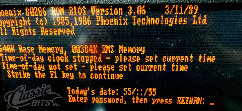
Replacing the Dallas type chip in my GRiDCase 1520 went very smoothly until I fired it up and was presented with a password prompt. By the way, I used a Maxim DS12887+ purchased fresh from DigiKey.

The BIOS password and the setting that determines if a password is enabled both are stored in CMOS memory. Since this was brand new memory it shouldn’t have such settings, right? Theoretically that would be correct but uninitialized bytes of memory are often 0xFF which from a technical standpoint would set the bit to enable a password and populate the stored password values with 0xFF.
I patched the BIOS to bypass the password, booted, dumped the CMOS contents, and confirmed that this was indeed the situation. I could have zeroed the CMOS at this point, or kept using the patched BIOS, but where’s the fun in that? I reverted back to the stock BIOS.
Further examination of the BIOS code revealed the algorithm used to encode/decode the stored password values. There is a static 8-byte table in the BIOS ROM of which each respective byte is XOR’d against the ASCII codes of the password. This table is the same in the GridCase 1520 and 1530 BIOS’s I examined, it’s located at 0xF0FC (or 0x70FC within a 32KB BIOS dump).

The table above shows that the decoded password for an uninitialized CMOS chip is ñ╗íùéáâ▓ which consists of special characters that didn’t exist on my keyboard. They can however still be inputted by holding ALT while typing the decimal ASCII code.

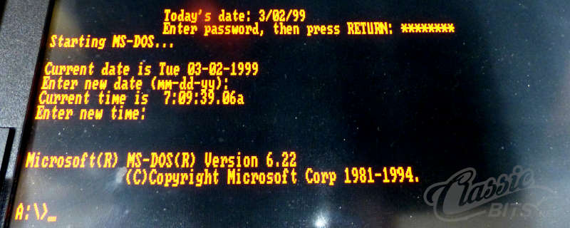
The password was successfully entered by typing ALT-164, ALT-187, ALT-161, ALT-151, ALT-130, ALT-160, ALT-131, ALT-178 and BINGO… the system booted.
Of course I didn’t want to do this every time (although what a hard password it would be to guess!) so the permanent solution was to initialize the CMOS to a proper baseline of all zeros. Most desktop computer have a jumper on the motherboard to reset the CMOS. Most laptop don’t (or they are undocumented).
NOTE: This project occurred before I became aware of the backdoor password present on many of these machines.
NOTE: The Maxim DS12887+ datasheet indicates how to clear the CMOS…
To clear the RAM, RCLR (Pin 21) must be forced to an input logic 0 during battery-backup mode when VCC is not applied. The RCLR function is designed to be used through a human interface (shorting to ground manually or by a switch) and not to be driven with external buffers. This pin is internally pulled up. Do not use an external pullup resistor on this pin.